General Instrument Information and Commissioning Instructions
Mercury iPS
The power supply for e1039 is an Oxford Instruments Mercury iPS (intelligent power supply), the manual for which is available here:
http://mymercurysupport.com/sites/default/files/59_UMC0072_01.pdf
The power supply includes one master unit, and one slave unit, each of which are capable of providing up to 40 A of current, or 80 A in parallel. The master has a touch screen and allows control of the magnet current from this front panel, while the slave listens for commands from the master and has no way to control it directly. On being initially commissioned, the master and slave should be connected by the provided DB-9 female to male cable, which goes from the DB-9 'out' port on the master to the DB-9 'in' port on the slave. The master should then be connected via the DB-27 RS232 cable to the computer which will be running the power supply control.
It is inadvisable to attempt to use the USB-B to USB-A connector to connect the master unit to the computer, as the associated driver seems to cause intermittent blue screen errors. If necessary, the power supply control can support this option, but it is best to use only the RS232 connection if possible.
At this point, you should connect the positive terminal of the master to the positive terminal of the slave by screwing in one of the flat metal busbars, and the negative terminals should be connected together with the other busbar. If it is desired to test the power supply while shorted before connecting it to the magnet, use the large copper braid to connect the two busbars, and the large brown resistor to connect the red and black terminals on the back of the Master unit. These two shorts should be removed before the power supply is connected to a real magnet. To connect to a real magnet, the positive terminal of the magnet cable should be connected to the positive busbar and the negative terminal to the negative busbar. Further, the switch heater in the magnet should be wired to the Red and Black terminals on the back of the master unit. For this configuration, the red and black terminals on the Slave unit are unnecessary.
At this point, a standard instrument power cable may be connected to the back of both power supplies, and the switches on the back of both units set to on. The Master may then be switched on by pressing the button on the front. It takes several minutes for the power supply to initialize at this stage, so please wait until the front panel displays readings for current and voltage and the like before attempting to do anything else.
To make sure the power supply is in remote mode, be sure the button in the lower left corner of the screen displaying a single letter is lit up Orange. If it is not, it must be pressed to change the power supply into remote operation mode.
USB Relay (Shim Control)
The other piece of equipment necessary to commission is the USB Relay board which allows the computer to control the switch heaters for the shim coils, which is a small metal box with alligator clips on the top labeled "USB Relay." This box may be connected to the computer via a provided USB-B to USB-A cable. The shim coils should then be connected to the alligator clips at the top of the USB Relay, with both ends of the circuit for the shim 1 switch heater connected to the clips next to the "1" label, and both ends of the circuit for the shim 2 switch heater connected to the clips next to the "2" label.
This board simply provides two circuit switches which may be opened or closed via the controlling computer, while the light next to each label indicates whether that switch is open or closed. If the light is on, the switch is open, and if it is off, the switch is closed. A small clicking noise is also audible when either switch opens or closes.
The USB Relay sometimes has troubles connecting to the computer the first time it is plugged in, so before attempting to ramp the magnet, it is important to verify that the computer can actually control the shim coils by watching the lights on the box. If the computer is unable to initially connect to the relay, simply unplug it and plug it back in after all other instruments have been connected to the computer. A tool for testing just the function of the relay board is available from the manufacturer at:
https://www.sainsmart.com/products/4-channel-5v-usb-relay-module
The Relay Board is a Sainsmart 4 channel 5v USB relay module, which is simply a board that, when powered, allows computer control to open or close one of four circuit switches. The casing it is in can be removed, and was simply made for ease of use and protection. The only modification made to the relay board as it comes from the manufacturer is, two pins on the top of the board were soldered together to connect the USB-B port to the power supply and allow the board to be powered simply by being plugged into the computer, rather than needing an external power supply. The case itself simply contains two holes for each of the two switches needed for the shims, and one to plug the USB-B plug through. It also contains alligator clips connected to switch 1 and switch 2 for ease of use, which are run through the holes above said switches, and fiber optic cables, which run directly up from the on-board lights that indicate whether a switch is open or closed, to provide the same indication to an observer outside the casing.
If necessary to build up from scratch, a Sainsmart board linked above may be used from scratch with no modifications, though it may be desirable to solder together the 5V pin and the USB power pin as described above, so that no external power supply is needed. On a fresh board straight from the manufacturer, the software described below will control Slot 1 and Slot 2, which are the furthest switch from the USB port, and the second furthest, respectively.
Labview Control
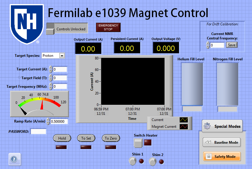
The computer control for the power supply and shims is a labview VI that uses the library of functional subVI's provided by Oxford Instruments for use with the Mercury iPS. Once properly commissioned, the control works to prevent dangerous situations from occurring with respect to the power supply. It also contains several controls for the shim coils, and possible use as a level meter, which will be described below.
Initial Connection
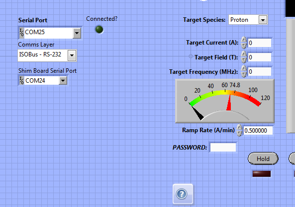
When initially loading the control on a new computer, most things should be automatically configured, but it will be necessary to tell the control what ports the Mercury iPS and USB Relay board are connected to, respectively. This can usually by identified on Windows by loading the device manager and looking at the list of COM ports, then looking at which number COM port disappears when you unplug each instrument respectively. Once everything is plugged in, set the Serial Port dropdown box to the COM port address of the power supply, and the Shim Board Serial Port dropdown box to the COM port address of the USB Relay board.
When you hit run on the VI, if everything is connected properly, the Connected? light should light up bright green, and you should see values near to 0.00 appearing for the current to the right. Further, by clicking the "Shim 1 and Shim 2" buttons, you should see a response from the lights on the USB Relay box itself (see Shim Control, below.)
Basic Operation
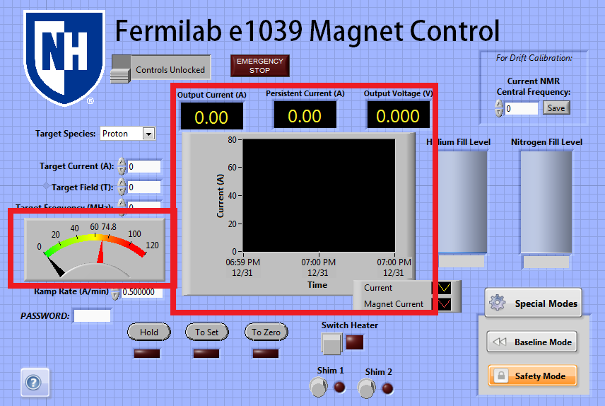
Once the control is properly connected to both the power supply and the shims, it reads out from the power supply several quantities:
Output Current: This value refers to the current in the leads, and matches the black needle on the left color dial. If the switch heater is on, this should match the value of Persistent Current.
Persistent Current: This value refers to the last current the power supply recorded leaving in the coils. It matches the value of the Output Current while the switch heater is on, but once the magnet is placed in persistent mode by turning off the switch heater, it serves as a reminder of where the current was left last time the power supply was used.
Output Voltage: This designates the voltage presently being provided by the power supply.
The value of Output Current and Persistent Current are recorded on the strip chart in the center of the screen so the behavior of the current can be monitored.
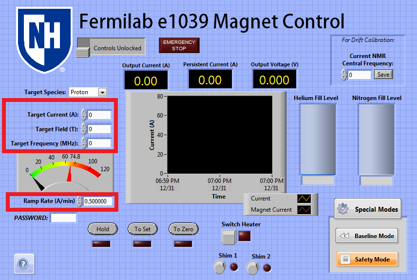
The power supply can be controlled by setting a Ramp Rate, and one of a Target Current, Field, or NMR Frequency. The ramp rate refers to the number of Amps per minute that the power supply attempts to match while ramping. Fast values of the ramp rate are dangerous at higher currents, so the control clamps this value to always be a safe one unless overridden by an expert. (See Safety Features, below.) The Target Current, Field, and Frequency all set the target current in the power supply, or, the current it attempts to reach while in 'To Set' mode. The target Field and Frequency simply change this value indirectly via the best calibration available.
Ramp Rate: The value in A/min that the power supply will ramp at while in To Set or To Zero mode. This may not exceed the following values:
| Allowed Ramp Rate | Output Current |
|---|---|
| 2 A/min | < 40 A |
| 1 A/min | 40-63 A |
| 0.5 A/min | > 63 A |
Target Current: The current the power supply will attempt to provide to the leads while in To Set mode. This may not exceed a value of 76.9 A.
Target Field: The value of the field the user wishes to achieve from the magnet, based on calibrations from the UVA cooldowns in January and June to convert this field into a desired current. To examine the drift of this field calibration, a box is available in the upper right corner which reads "For Drift Calibration." If the user occasionally enters the value of the target signal's frequency displayed from the NMR system, the control will automatically log this information and update the Target Field calibration.
Target Frequency: The frequency which the user wishes to see the target signal at, based on most recent calibrations. The box above all numerical controls allows the user to switch the target species between Proton and Deuteron, which updates what the calibration is that converts target frequency into target field (and subsequently, into target current.)
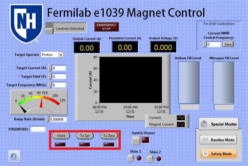
The power supply can be in one of three modes while it is turned on: Hold, To Set, and To Zero. When the power supply is first turned on, its output will be clamped for safety, which is signified by the 'Hold' light blinking yellow. The lights below each relevant button otherwise indicate what mode the power supply is in.
Hold: The default state of the power supply. In this state the current in the leads will be locked at whatever their current value, the value displayed under 'Output Current', is. In case the user is unsure what they are doing or if an unexpected event occurs, they should always switch the power supply to Hold until it is safe to continue ramping.
To Set: While in this state, the power supply will ramp until it reaches the current value displayed in the "Target Current" field. Once it reaches this value, it will switch to Hold mode automatically. We have observed the behavior of the power supply is such that after switching to hold, it takes a minute or so for the current to stabilize at the set point, as it overshoots and undershoots several times as it nears the set point. If the switch heater is off, the power supply will ramp very fast, if it is on, it will ramp at the rate set in "Ramp Rate."
To Zero: While in To Zero state, the power supply will ramp the leads towards a value of zero current. On reaching an output current of zero, it will switch to Hold mode automatically. If the switch heater is off, the power supply will ramp very fast, if it is on, it will ramp at the rate set in "Ramp Rate."
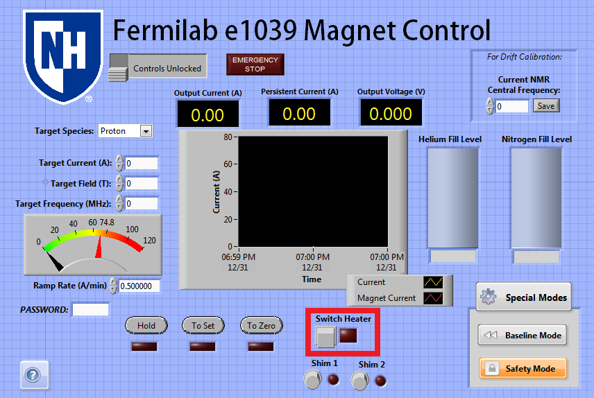
Finally, the power supply's Switch Heater can be turned on using the square button marked Switch Heater. If the switch heater is off, the power supply will be essentially shorted, and can ramp the leads up or down as it pleases, to actually ramp the magnet, it is necessary for the switch heater to be on. On clicking the square button, the switch heater will be turned on if it is off, or off if it is on. The switch heater takes time to open or close, so on hitting the button, a 30-second timer will be displayed on the screen, locking out other actions until the switch heater has completed changing state. The light next to the button indicates a read back from the power supply as to whether the switch heater has successfully opened or not. If the light is green, the switch heater is on, and if it is red, the switch heater is off.
If the switch heater is on, then ramping the output current by using "To Set" or "To Zero" will ramp the current in the magnet itself. If the switch heater is turned off while the current has been driven to some nonzero current, the magnet will be left in persistent mode. The current value displayed in "Persistent Current" logs the last known value of the current before the switch heater was turned off. Allowing for small field drifts, this should be roughly the current in the coils at any future time. It is unsafe to turn the switch heater on while the current in the leads and the current in the coils differ, so the user is locked out from changing the state of the switch heater unless the current and persistent current match within error bars.
The user is also unable to turn the switch heater on or off unless the power supply is in "Hold" state.
Shim Control
![]()
The USB Relay can also be used to control the state of the shim coils, using this same control. Pressing the Shim 1 button will open the switch for Slot 1 on the USB Relay, turning on Shim 1 if everything is connected properly. Pressing it again will turn Shim 1 off. Similarly, the Shim 2 button can be used to turn the second shim coil on or off. Note that in this case, the light next to the buttons only indicates the last command the computer knows it has sent to the shim coils, so it will be on if it last told them to turn on, and off if it last told them to turn off. If there is a cable connection that is lost or damaged, there is presently no way for the computer to determine that the shim is not actually on.
The state of the shim coils is also changed automatically by using the other features of the power supply control. When the Switch Heater is turned on, both Shim 1 and Shim 2 are also turned on, and when the main Switch Heater is turned off, both Shim 1 and Shim 2 are both turned off. Further, to prevent moving the field without both shim coils being on, if the user switches the power supply to "To Set" or "To Zero" while the switch heater is on, Shim 1 and Shim 2 will both be turned on, and locked from being turned off until the power supply is back in Hold mode. This means the shim coils may only be off at any point while the power supply is in Hold mode, and otherwise will be automatically turned on.
Safety Features
The control contains several safety features, in addition to those already described in the Switch Heater and Shim Control sections.
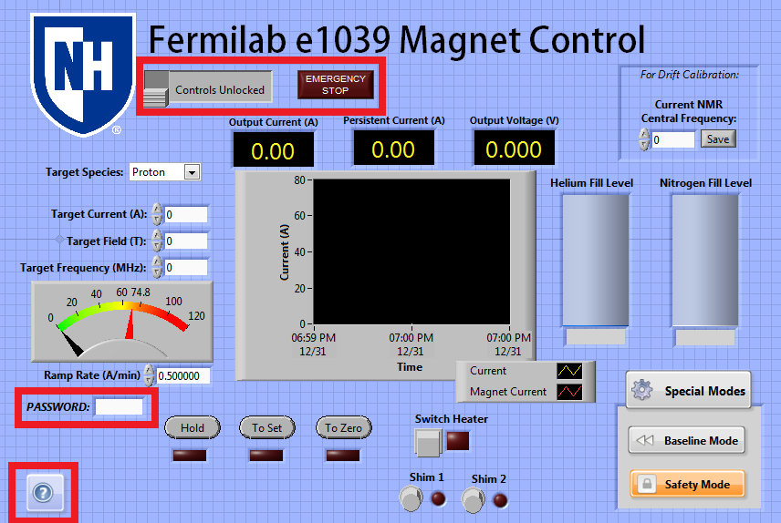
[?]: The ? button in the bottom left will display a small box of instructions and information about the VI for quick reference, if the user clicks and holds on the button.
Control Lock: The grey switch under the title will lock or unlock all controls from being used. If it is toggled on, all controls will be greyed out and unusable until the control lock is turned off. This is to prevent accidentally sending commands to the power supply, and should be used when the control is not actively in use.
Emergency Stop: In an emergency situation where the integrity of the VI is not trusted, the EMERGENCY STOP button in the top of the screen can be clicked to abort any current processes. On clicking this button the power supply will be switched to Hold mode, and then the Labview control will be instantaneously aborted from running, preventing further commands. This should primarily be used if the user believes that the VI itself is doing something unsafe. If the power supply itself is doing something unsafe and sending the hold command regularly is not doing anything, pressing the Emergency Stop button should have no effect either.
Password: If the Admin password is entered into this field correctly, several safety features of the labview control will become disabled or editable. Primarily, while the password in the box is correct, the user can type any ramp rate and current into the target current and ramp rate boxes, even if these values exceed the guidelines given in that section. Additionally, the timer built in for "Safety Mode" will become editable, appearing on the left of the Safety Mode button (see below.) The password box will be cleared automatically ten minutes after the user enters it, and must be entered again if it is necessary to exceed the safety values of the control for longer than ten minutes.
Special Modes
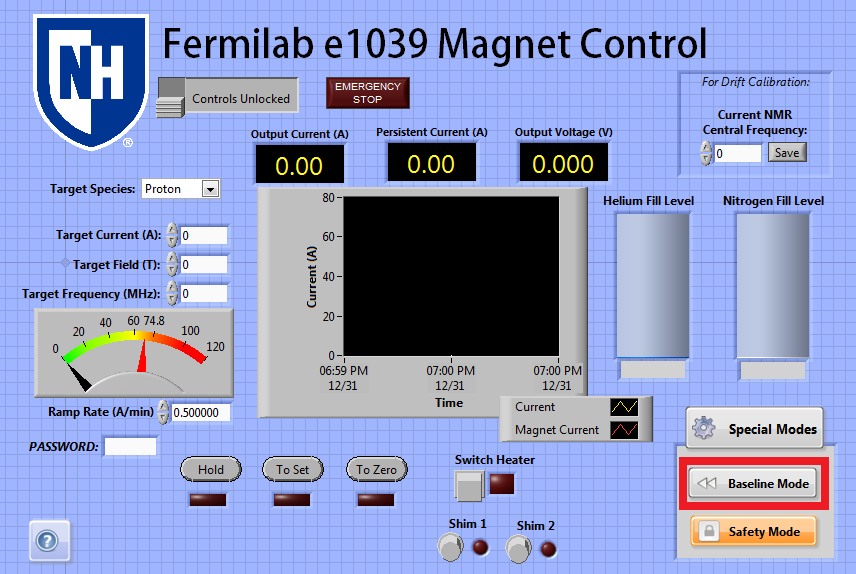
The labview module contains support for several special modes which may be toggled on or off as the user wishes. The box containing these special modes may be closed by pressing the Special Modes button itself, to make accessing them require more clicks and prevent accidentally activating them.
Baseline Mode: This button exists for the purposes of quickly taking a baseline once the magnet is at field. On baseline mode being turned on, the current will ramp to 1 A below the set point at the fastest safe rate possible. If the switch heater is off, it will be turned on and then ramp 1 A down, if it is on, the power supply will simply ramp 1 A down. On baseline mode being toggled off, the current will ramp back to the set point-- again, if the switch heater is off, it will first be turned on. While baseline mode is on, the "Output Current" box flashes, and a large warning reading "Baseline Mode" appears over the color dial on the left, so the user cannot mistake the 1 A lowered current for the actual current at the set point.
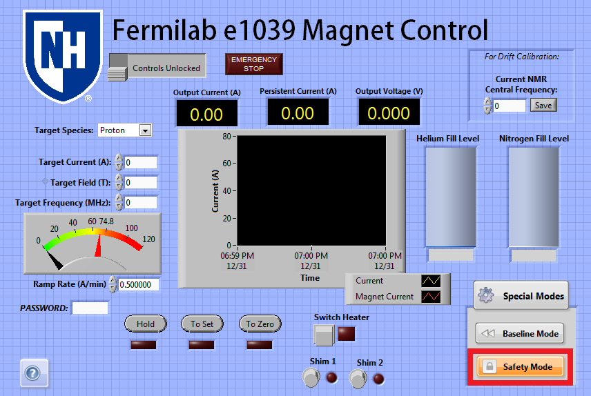
Safety Mode: This mode is on by default, but can be toggled off by pressing the Safety Mode button. While Safety Mode is on, an internal timer is started, which resets any time an action is taken within the labview control. After 20 minutes of inactivity, if Safety Mode is on, the Switch Heater will be automatically turned off to switch the magnet into persistent mode, providing conditions are safe for it to be disabled. This 'timeout' duration may be changed to any number of minutes if the Admin password is entered.
As when toggling the switch heater directly, a 30 second timer will activate if either of these modes has to change the state of the switch heater.
Level Monitor
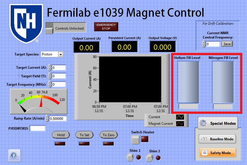
Lastly, the power supply and the control support additional use as a level meter. A nitrogen and helium level monitor card is installed inside the master unit of the power supply, so if connected to a level probe, the iPS will send the resulting measured level to the tanks on the main screen of the control. This feature has been mostly untested but may provide an additional level monitor if needed.
Transient Timer Issue
Over its lifetime being tested by e1039 collaborators, the power supply has mostly behaved well, but had two isolated incidents of odd behavior, one in January 2018 during a UVA cooldown, and on in August 2018 during a UNH cooldown.
The January 2018 issue is documented as:
"The power supply suddenly and quickly ramped down from field to a value close to zero, and then shortly after, began to ramp up very quickly until it passed the set point, causing a quench."
While the August 2018 issue is described as:
"During a ramp down, the power supply suddenly jumped from an output current of 17 A to an output current of 2 A when the switch heater cable was momentarily disconnected. Due to a field probe in the magnet itself, we could tell the current was actually still 17 A. Both the power supply reading and field probe reading were slowly approaching a current of zero, as directed by the control. After 10 minutes ramping down, when there was approximately 1 A in the coils, the magnet suddenly ramped down to a value of -16 A with no user input, at which point the power supply and field probe agreed, and the switch heater was turned off. At this point we were able to ramp to zero without a quench."
We currently believe that both of these issues are as a result of a strange value set for the transient timer. Upon testing the power supply after the August 2018 issue, it was determined that if the switch heater cable becomes momentarily disconnected during a ramp, the power supply becomes confused about the actual value of the current and displays an erroneous value. This was the cause of the August 2018 issue, and may be related to the January 2018 issue, but the common factor between both appears to be the power supply's behavior after detecting a problem. The switch heater cable being disconnected would normally cause the power supply to detect a quench and begin internal safety procedures, as would any unsafe situation which occurred in January. However, the power supply's behavior is such that on measuring dangerous conditions, it logs the current, and then waits the duration of an internally configured "Transient Timer" before acting to try and fix the situation, to prevent false positive quenches. Further, it acts based on the initially measured current, which may lead it to ramp to values below zero or above the set point, if the output current has been changed at all by the user since the transient timer started. We believe this is consistent with the issue observed in August, and may also be consistent with the issue observed in January.
For both incidents, the value of the transient timer was set to 10 minutes, even though the manual advises a maximum value of 3 seconds. This allowed for a very long time for the current to change drastically from what it was when quench conditions started. We have tested and been able to replicate the issue from the August cooldown with a dummy setup, and showed that it cannot occur once the transient timer is set to a safe value of 3 seconds.
The transient timer has been currently set to the safer value of 3 seconds. This has hopefully resolved the root cause of both incidents.