NMR Cables & Coils
to be written.
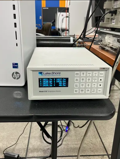
Lakeshore 218 manual: 218_manual.pdf
Temperature Sensors
We utilize two types of the temperature sensors;
- Vishay RCWP, 1K Ohm Chip Resistor
- Cernox sensor
- Spec sheet: lstc_cernox_l.pdf
- Model(s) that we have: CX-1030-SD
- Four wires (V+, I+, V- & I-) per sensor
- https://twist.phys.virginia.edu/work/Drell-Yan/Manuals/CernoxInstallation.pdf
- LakeShore 218 Manual 218_manual.pdf
We plan to arrange a set of sensors per insert as follows;
- Top cup: Chip, Chip, Chip, Cernox
- Center cup: None
- Bottom cup: Chip, Chip, Chip, Cernox
Readout
Target Insert:
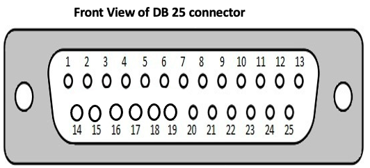
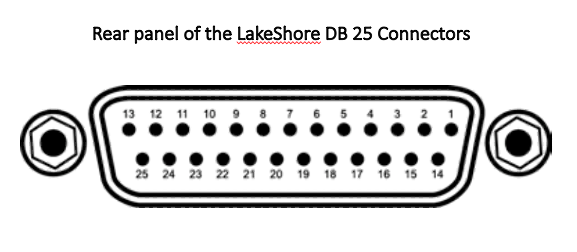
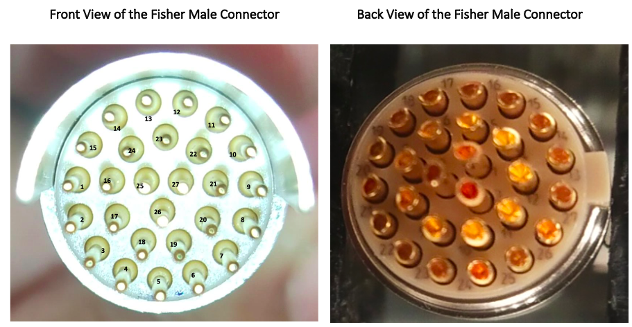
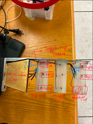
The target insert has three PTFE target cups, and each cup is housed with three NMR coils. These NMR coils are started from the top of the target insert, with the SMA connectors routed from inside the shell of the insert and end on the target cups. The top and bottom cups are housed in three-chip resistors, and the Cernox and the middle cup do not have any sensors. These sensors are reading through the LakeShore 218 via the fisher connector housed at the top of the insert. The fisher (female) connector is attached through the small wires routed inside the insert shell and connected to the sensors on the target cups. To read these sensors, a cable is required that has a fisher (male) connector, and the other end has two DB 25 (male) connectors to connect to the rear panel on the lakeshore DB 25 (female) connectors. For this purpose, the fisher (female) on the insert and the fisher (male) on the cable should be on the same pin configuration. The pin assignment for the target is explained below:
- These eight sensors are read out by one of LakeShore 218 through
One Fischer connector (27 pins) at the insert side and
Two D25 (female) connectors at the LakeShore 218 side.
- The readout cable comprises 20 conductors at minimum (2 wires * 6 chip resistors (12 wires) + 4 wires * 2 Cernox (8 wires)).
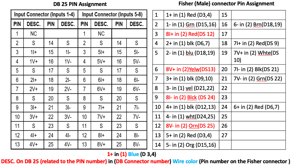
Mapping between the sensors and the Lakeshore readout:
Eight sensors (6 chip resistors and 2 Cernox) are connected to the eight channels on the Lakeshore 218 readout. The target cups are numbered from 1 to 9, showing the chip resistors' location as shown in the attached picture. The following table reflects the mapping between the sensors on the target cups and the lakeshore channels.
Mapping table between the sensors and the Lakeshore channels:
| Sensors | Cup | Lakeshore Channel |
|---|---|---|
| Chip resistor 1 | Bottom Cup | 1 |
| Chip resistor 2 | Bottom Cup | 2 |
| Chip resistor 3 | Bottom Cup | 3 |
| Chip resistor 4 | Top Cup | 4 |
| Chip resistor 5 | Top Cup | 5 |
| Chip resistor 6 | Top Cup | 6 |
| Top Cernox | Top Cup | 7 |
| Bottom Cernox | Bottom Cup | 8 |
Spare parts Information
Information relevant to spare parts is mentioned below:
| Part/Reference Number | Name | URL | Spare Counts |
|---|---|---|---|
| 104497 | DBEE 105 A102-130 (Female 27 Pole) | Product Finder | (fischerconnectors.com) | 5 |
| 104457 | S 105 A102-130+ (Male 27 Pole) | Product Finder | (fischerconnectors.com) | 5 |