| Table of Contents |
|---|
General Instrument Information and Commissioning Instructions
Mercury iPS
The power supply for e1039 is an Oxford Instruments Mercury iPS (intelligent power supply), the manual for which is available here:
...
To make sure the power supply is in remote mode, be sure the button in the lower left corner of the screen displaying a single letter is lit up Orange. If it is not, it must be pressed to change the power supply into remote operation mode.
USB Relay
The other piece of equipment necessary to commission is the USB Relay board which allows the computer to control the switch heaters for the shim coils, which is a small metal box with alligator clips on the top labeled "USB Relay." This box may be connected to the computer via a provided USB-B to USB-A cable. The shim coils should then be connected to the alligator clips at the top of the USB Relay, with both ends of the circuit for the shim 1 switch heater connected to the clips next to the "1" label, and both ends of the circuit for the shim 2 switch heater connected to the clips next to the "2" label.
...
https://www.sainsmart.com/products/4-channel-5v-usb-relay-module
Labview Control
The computer control for the power supply and shims is a labview VI that uses the library of functional subVI's provided by Oxford Instruments for use with the Mercury iPS. Once properly commissioned, the control works to prevent dangerous situations from occurring with respect to the power supply. It also contains several controls for the shim coils, and possible use as a level meter, which will be described below.
Initial Connection
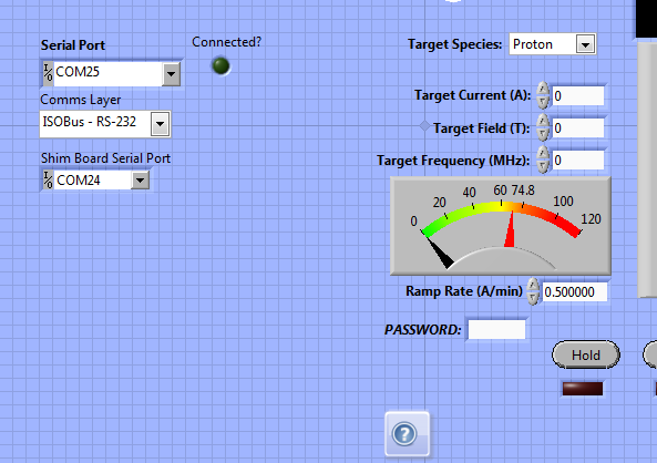
When initially loading the control on a new computer, most things should be automatically configured, but it will be necessary to tell the control what ports the Mercury iPS and USB Relay board are connected to, respectively. This can usually by identified on Windows by loading the device manager and looking at the list of COM ports, then looking at which number COM port disappears when you unplug each instrument respectively. Once everything is plugged in, set the Serial Port dropdown box to the COM port address of the power supply, and the Shim Board Serial Port dropdown box to the COM port address of the USB Relay board.
When you hit run on the VI, if everything is connected properly, the Connected? light should light up bright green, and you should see values near to 0.00 appearing for the current to the right. Further, by clicking the "Shim 1 and Shim 2" buttons, you should see a response from the lights on the USB Relay box itself (see Shim Control, below.)
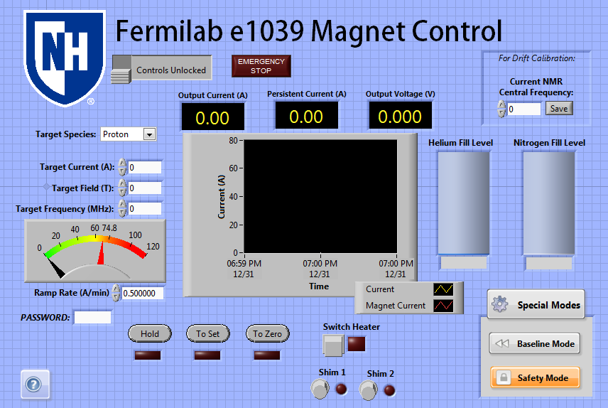
Basic Operation
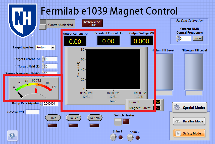
Once the control is properly connected to both the power supply and the shims, it reads out from the power supply several quantities:
...
The user is also unable to turn the switch heater on or off unless the power supply is in "Hold" state.
Shim Control
![]()
The USB Relay can also be used to control the state of the shim coils, using this same control. Pressing the Shim 1 button will open the switch for Slot 1 on the USB Relay, turning on Shim 1 if everything is connected properly. Pressing it again will turn Shim 1 off. Similarly, the Shim 2 button can be used to turn the second shim coil on or off. Note that in this case, the light next to the buttons only indicates the last command the computer knows it has sent to the shim coils, so it will be on if it last told them to turn on, and off if it last told them to turn off. If there is a cable connection that is lost or damaged, there is presently no way for the computer to determine that the shim is not actually on.
The state of the shim coils is also changed automatically by using the other features of the power supply control. When the Switch Heater is turned on, both Shim 1 and Shim 2 are also turned on, and when the main Switch Heater is turned off, both Shim 1 and Shim 2 are both turned off. Further, to prevent moving the field without both shim coils being on, if the user switches the power supply to "To Set" or "To Zero" while the switch heater is on, Shim 1 and Shim 2 will both be turned on, and locked from being turned off until the power supply is back in Hold mode. This means the shim coils may only be off at any point while the power supply is in Hold mode, and otherwise will be automatically turned on.
Safety Features
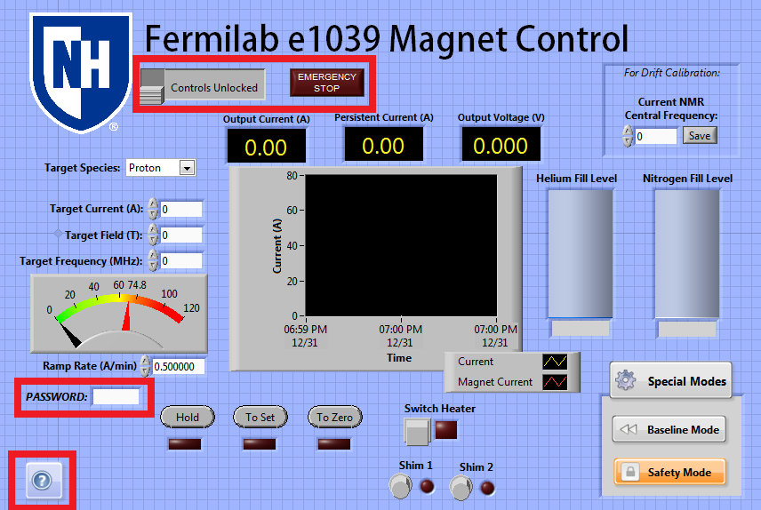
The control contains several safety features, in addition to those already described in the Switch Heater and Shim Control sections.
...
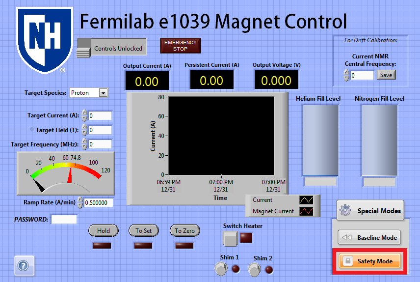
Password: If the Admin password is entered into this field correctly, several safety features of the labview control will become disabled or editable. Primarily, while the password in the box is correct, the user can type any ramp rate and current into the target current and ramp rate boxes, even if these values exceed the guidelines given in that section. Additionally, the timer built in for "Safety Mode" will become editable, appearing on the left of the Safety Mode button (see below.) The password box will be cleared automatically ten minutes after the user enters it, and must be entered again if it is necessary to exceed the safety values of the control for longer than ten minutes.
Special Modes
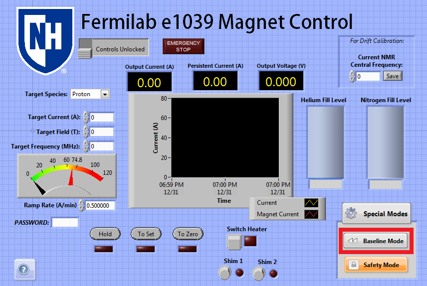
The labview module contains support for several special modes which may be toggled on or off as the user wishes. The box containing these special modes may be closed by pressing the Special Modes button itself, to make accessing them require more clicks and prevent accidentally activating them.
...
As when toggling the switch heater directly, a 30 second timer will activate if either of these modes has to change the state of the switch heater.
Level Monitor
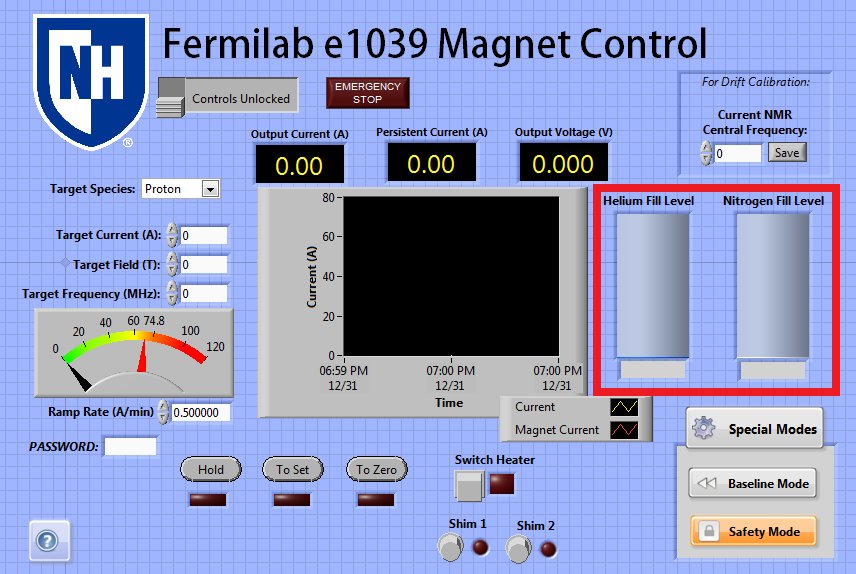
Lastly, the power supply and the control support additional use as a level meter. A nitrogen and helium level monitor card is installed inside the master unit of the power supply, so if connected to a level probe, the iPS will send the resulting measured level to the tanks on the main screen of the control. This feature has been mostly untested but may provide an additional level monitor if needed.
Transient Timer Issue
Over its lifetime being tested by e1039 collaborators, the power supply has mostly behaved well, but had two isolated incidents of odd behavior, one in January 2018 during a UVA cooldown, and on in August 2018 during a UNH cooldown.
...