...
- Make sure both Liquefiers are on "Idle" mode.
See the QT HMI main screen (see Fig 1a). If QLHe100A and QLHe100B says "Idle" then both liquefiers are on idle mode. If any of those statuses are different from "Idle". Then navigate to the Liquefier's screen (Fig 1c).
By touching the "Quantum technology" box (top-left of Fig 1a), and then touching the Liquefier name box (see Fig 1b).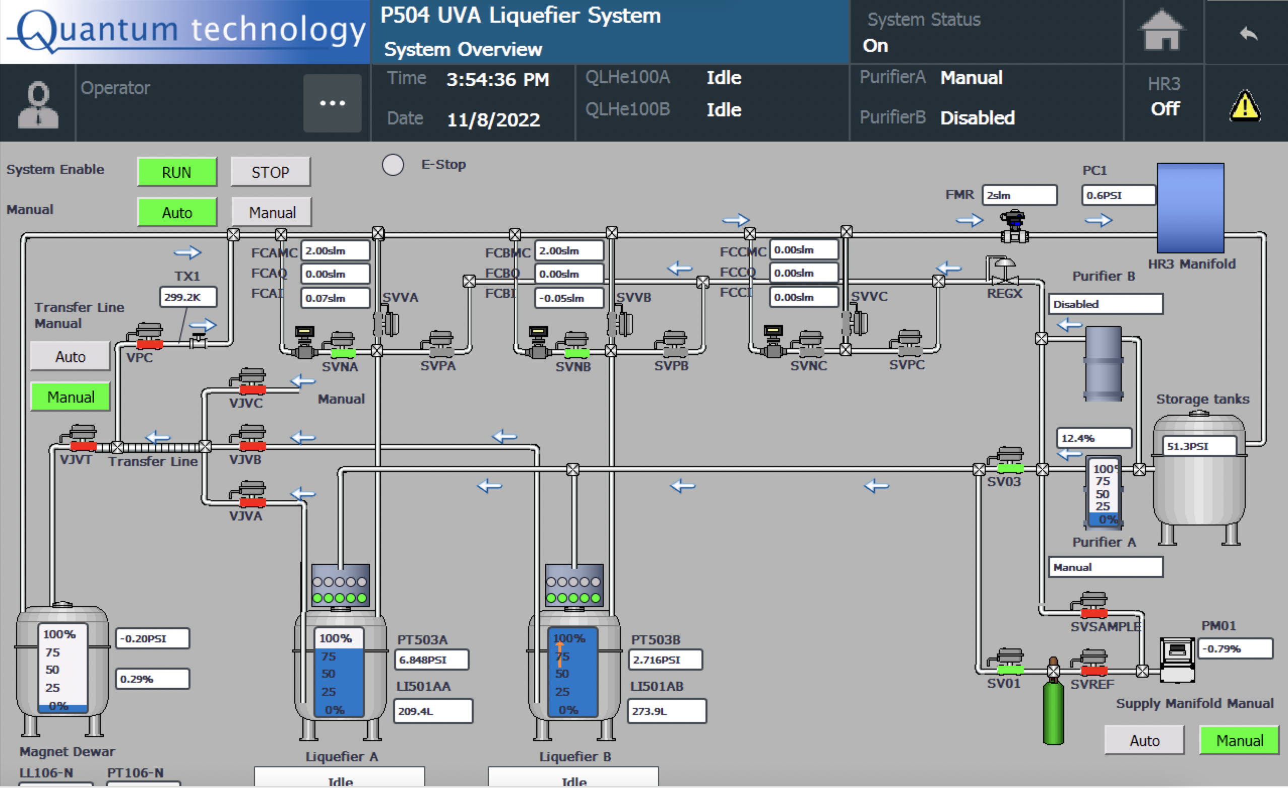
Fig (1a)
Fig (1b)
Then, Click on the "Idle" button on the top-left corner of Fig 1c.
Fig (1c) - Turn ON purifier LN2 heater by clicking/touching the "Heater MC Cycle" button (see Fig 2a). Check whether "VNVA" is open (it is normally kept open), if not open "VNVA".
You will see that the bottom part of the purifier (in Fig 2a) becomes "orange" and "Heater MC Cycle" becomes "green".
Wait until the level drops down to <2% and also TA_Top and TA_Bottom reads > 273 K.
Fig 2a
You can keep the heater ON without cycling by pressing both buttons (see Fig 3 below).
Fig 2b
Don't for get to switch to the heater cycles if you are not watching frequently (eg: when you go to sleep, turn off the bottom one)
Fig 2c - Close v30 and v35 hand valves on HR3 (as shown in Fig 3) to isolate the helium space inside the purifier.
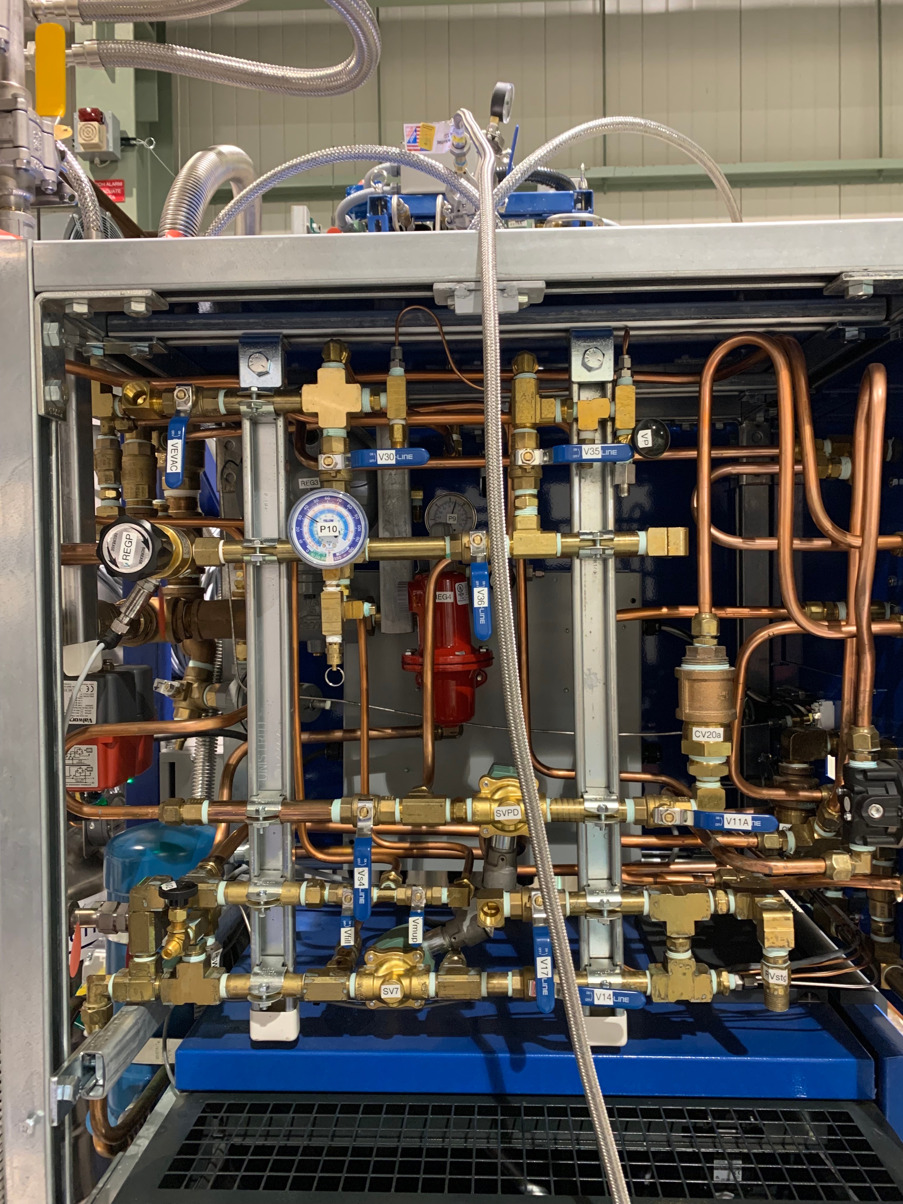
Fig 3 - Close BV02 hand valve to isolate the Liquefiers (see Fig 4 bottom left 'yellow' hand valve).
Note: The pressure inside the purifier gHe space maybe at very high pressure (~50 psi or higher: Check the reading on p10 on HR3 manifold).
Therefore, before opening the v10a to start the first cycle of pumping, we want to make sure that we isolate the purifier and relieve the pressure down to ~1 psi (or slightly above the atmosphere). - Slightly open the hand-valve called "Vvent" on the Helium supply manifold (see Fig 5), and listen to the sound generated by relieving gHe from that vent when you open "Vvent".
When the relief sounds get low in volume, that indicates that the pressure inside the purifier gHe space is close to the atmosphere.
(Note that, In the Fig 5, Vvent is fully open, and you don't need to fully open)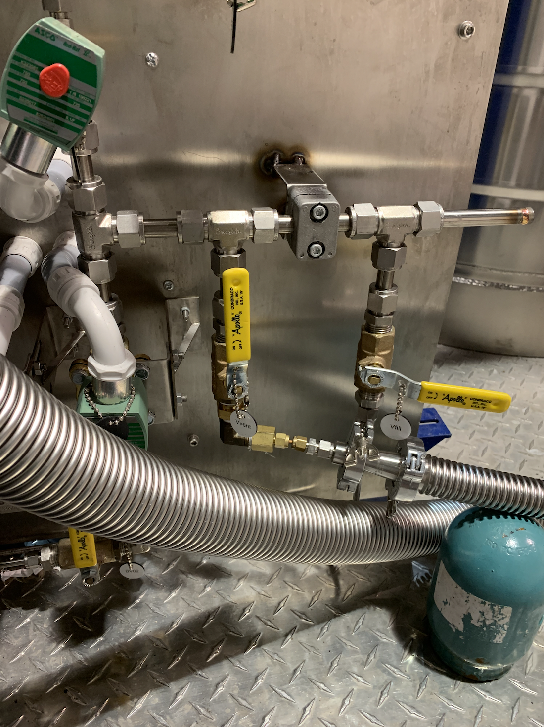
Fig 5 - Once v10a is opened, and heaters are ON, then let LN2 to boil-off while venting the contaminants through v10a.
This will take about 8hrs to empty the LN2 but a bit longer for the TA_top and TA_bottom to reach 273K.
Fig 6: This should be the configuration of v9a, v21a and v10a while pumping and purging, and ensure v30 and v35 hand valves are closed before pumping/purging.
- Install pumping and purging setup (see Fig 7a and 7b below). A gHe bottle, the pump (green), and a pressure gauge need to be connected with two separate hand valves to open/close pump and gHe-supply (to purge) independently. In this step, do not open any solenoid valves on the QT-HMI, just only install the setup and proceed to the next steps.
Note: it would be better if you use an electronic pressure gauge (eg: MKS sensor with the readout) instead of the mechanical gauge because some mechanical gauges can measure max. pressure as 15 psi.
Therefore, these lower/smaller ranged gauges can mislead us.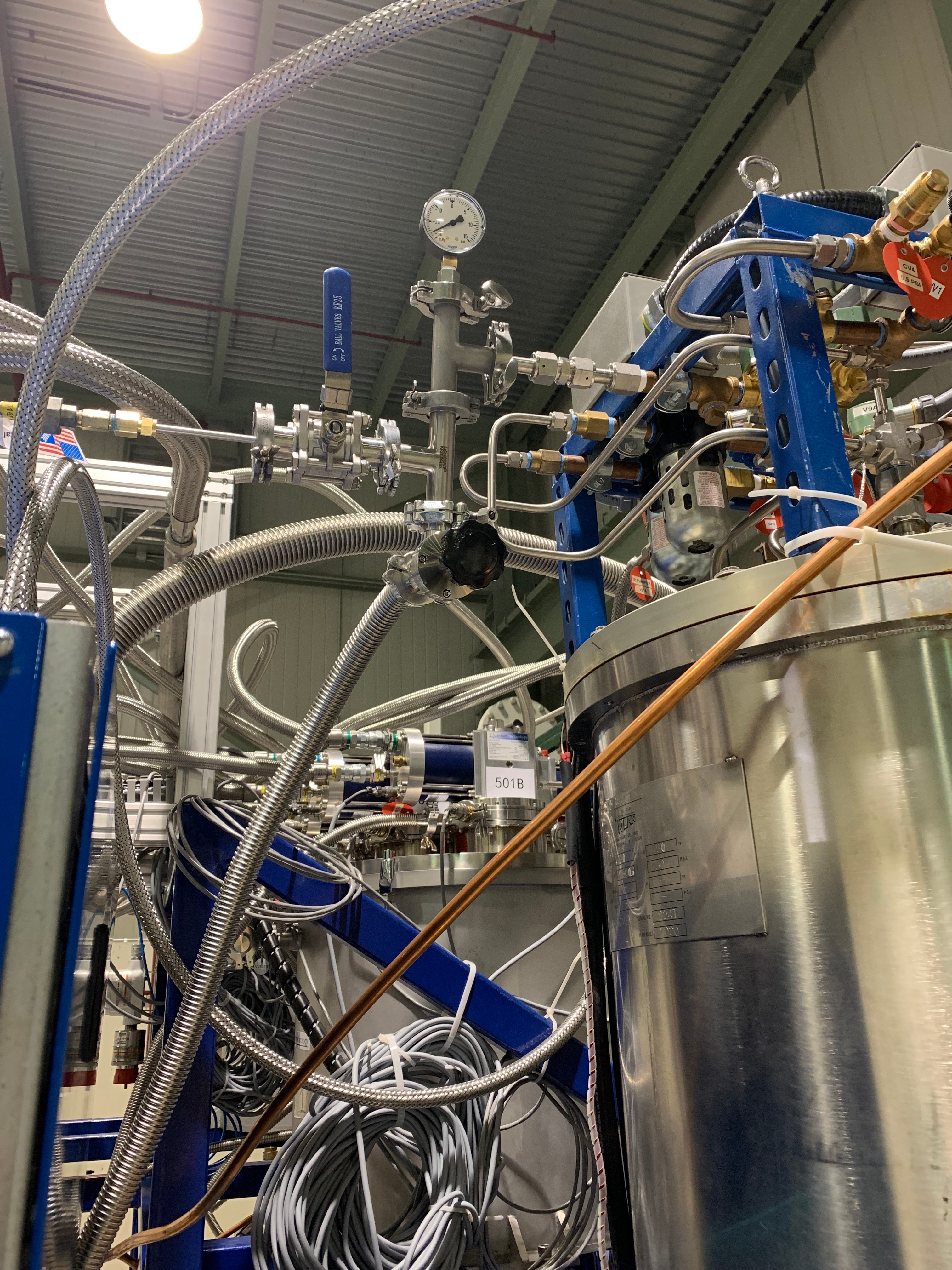

Fig 7a Fig 7b
- Start (green) pump and open the hand valve connects to the pump to pump down while the heater on purifier LN2 is ON (see Figa 3a for the hand-valve (black) to the green pump).
- Wait until the pressure on the gauge (pump-purge manifold: see Fig 3a) goes down to the lowest (usually it takes about 15-20 mins).
- Close the black-hand-valve to the green pump (you don't have to turn off the power to the pump, just keep it running as you will pump again in this procedure).
- Regulate the pressure of the gHe bottle ~3 psi and then open the blue-hand-valve (see Fig 3a) to purge the purifier gHe space.
- Close the blue-hand-valve when the pressure gauge reads ~3 psi.
- Open the black-hand-valve to start pumping down.
- Repeat Steps 9 → 12 as many times as you wanted.
- After done with the last cycle of pumping, Close the black-hand-valve to the green pump.
- Regulate the pressure of the gHe bottle ~3 psi and then open the blue-hand-valve (see Fig 3a) to purge the purifier gHe space.
- Close v10a on QT-HMI screen (see Fig 6a).
- Open v30 hand-valve slowly until it is fully opened (see Fig 4a), and watch the pressure on p10. It will go up to the outside tank pressure.
- Check the pressures on p41 and p40 on the HR3 front. Both should read the same value.
*****************************************************************************************************************************
*****************************************************************************************************************************
************************************** Please note that the information below are some previous notes *********************
- Cleaning the QT purifier Helium-space from the top of the purifier Dewar when the both Liquefiers are on "Idle" mode
a) Make sure both Liquefiers are in Idle mode.
b) Make sure "VNVA" is open on purifier LN2 space, and then turn ON the heaters to vent all the LN2 as gN2.
c) Close V30 and keep V35 Open
d) Open SV01 in the QT HMI overview screen
e) Close BV02 hand valve to isolate the Liquefiers
f) Connect a KF hose from the manifold (see the image below) to the port which connects to the GV02 yellow hand valve.

g) Open (a little bit) the 'vent' hand valve on that manifold and then open the black hand valve and yellow hand valve (GV02).
h) Check the FMR reading (it will go up and slowly decrease as the gHe in the purifier flow through). Once the FMR shows around ~4slm (also on the QT HMI), then that indicates that the gHe from the purifier space is close to empty; and it's ready for pump, purge.
i) Close V30 and V35 on HR3 manifold.
j) Connect the pump-purge-manifold with a pump, and gHe cylinder to the port on V10a.
The above steps (c) to ( i ) allow us to avoid the sudden pressure drop when opening the V10a. Otherwise
Before connecting the pump, open V10a solenoid valve and vent the gHe inside the purifier space to the outside, and leave V10a open.
k) Close the gHe (purge) hand-valve, and start the pump to pump down → Then close pump-hand-valve and purge the purifier Helium space with ~3psi by opening purge-hand-valve.
l) Iterate step (e) several times.
m) Turn OFF the purifier heaters.
n) Backfill the purifier Helium space with gHe (~6psi)
o) Close V10a solenoid valve.
p) Open V30 slowly, and then open V35.
...