Here are your 5 duties: Maintain Polarization, Maintain Cryogens, Move Target, Respond to Alarms, Log Everything.
Your first task on shift is to talk to the outgoing target operator and read the Fermilab elog! (https://dbweb8.fnal.gov:8443/ECL/spin_quest/U/login) Find out the following.
- What target are we on?
- What is the calibration constant and baseline we are using?
- What is the encoder position for that target?
- What frequency has provided the best polarization?
- What alarms have occurred? How have they been addressed?
- Is anything else different about the target today?
- What target are we on?
Next make sure all the necessary control screens are up. You should have PDP, the Cryo Controls, strip charts, and the alarm handler accessible.
Maintain Polarization
The polarization should be your constant worry. Even once you've found a good microwave frequency for the material, be vigilant! This frequency will change as the sample acquires dose!
Your constant attention to the microwave frequency is required! Change it often to ensure you have the highest polarization!
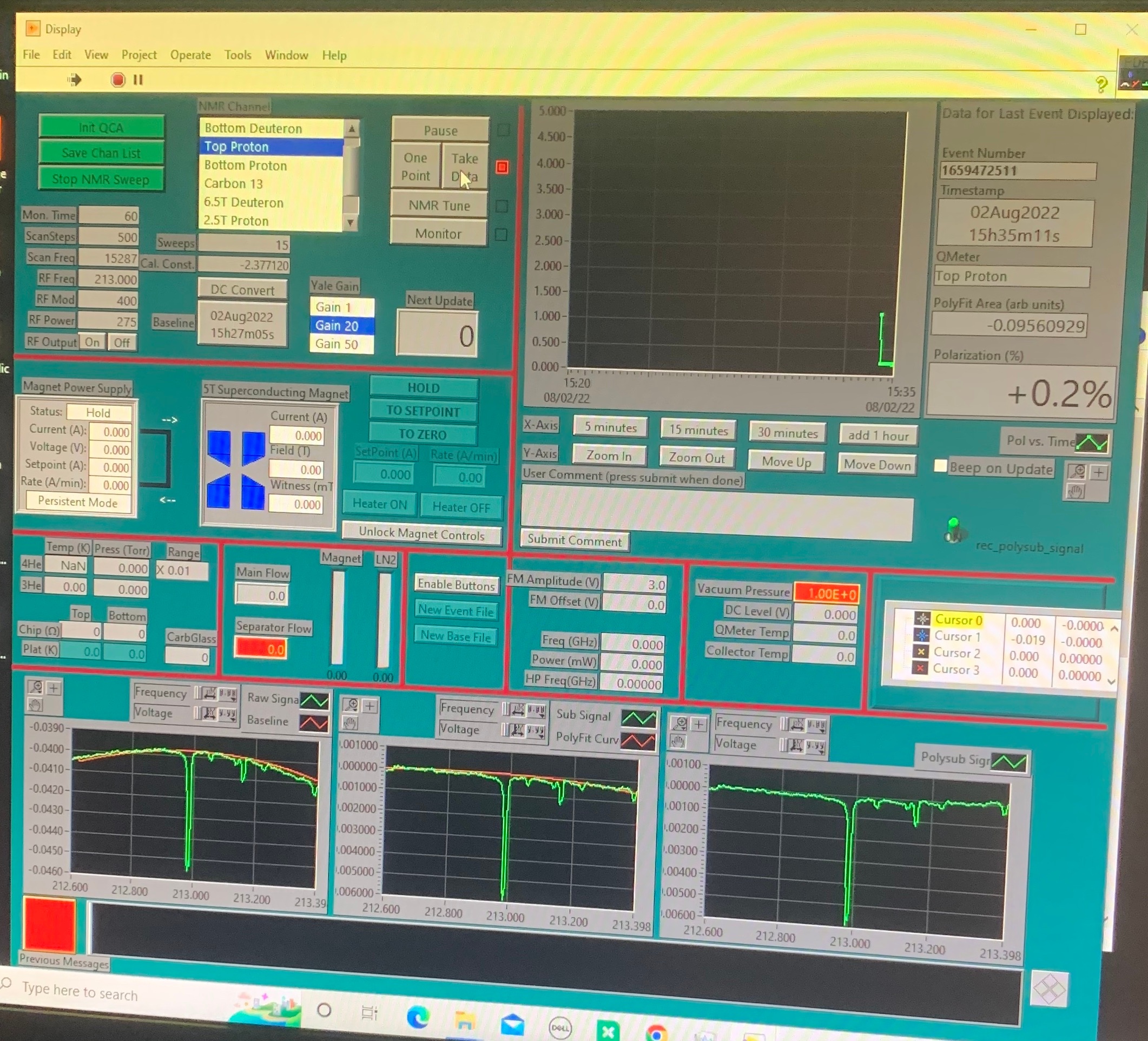
NMR
- The NMR system is how we monitor the polarization. Read the PDP overview for a tour of the software we use for NMR.
- "Take Data" to run the NMR, and hit "DC Convert" when you need to recenter the signal.
Microwaves
The output frequency of the microwave is automatically controlled by the microwave VI. It takes the real-time polarization data recorded by the PDP via "Data input file".
Call the target expert if
- The microwave VI shows any error, which is usually marked with red color.
The polarization is going down continuously for longer than 5 minutes.
User Interface of Microwave VI

Maintain Cryogens
The cryogens are maintained by automatic PID loops. Your job is generally to monitor these loops and step in if they fail.
Nose Level
- Keeping the Liquid Helium above the targets is crucial.
If the level drops below a target cup, the polarization will drop to zero!
- With both the beam and microwaves on, there is a large heat load evaporating helium.
- A PID loop should automatically adjust the run and separator valves to maintain appropriate levels.
- If the PID loop is not working, it is your job to adjust the run and separator valves to keep the target running.
- If the liquid level probe is not working, you can use the platinum resistors readings in PDP.
- Use the flows out of the fridge to anticipate changes in liquid level.
- The separator flow (FI91127) is usually good around 5-10.
- The main flow (FI91148) will change with the heat load of microwaves and beam. With both on, 20's is good.
- Keep the separator flow higher than the fridge flow in most cases.
- These values are guides, and may not always be best for all situations.
Magnet Liquid Level
- The magnet helium and nitrogen levels are controlled automatically.
Ensure the levels stay within alarmed levels. If they drop too low or go too high, wait to see if the alarms go away. If they don't contact a target expert.
Space ID Low High Fill Procedure Magnet LHe anifolds Magnet Dewar Level 10% 45% https://seaquest-docdb.fnal.gov/cgi-bin/sso/ShowDocument?docid=9670 Magnet LN2 LL106-N 40% 90% https://seaquest-docdb.fnal.gov/cgi-bin/sso/ShowDocument?docid=10337 There are 4 levels to watch
- Magnet Helium (LL91111)
- Magnet Nitrogen (LL91110)
- Buffer Dewar Helium (LL91101)
- Nose Level (LL91112)
QT System
Set of slides with operational settings: QT_Operational_Settings.pdf
The first thing (on the UVA-QT system) to check is the overall status of the system on QT-HMI, and the main part of the screen is the following.
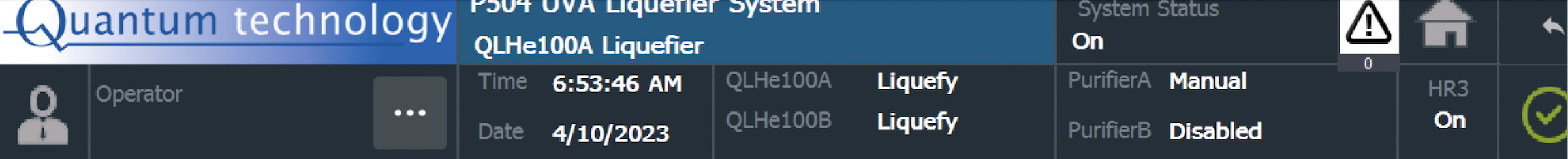
System status: "ON"
Both Liquefiers: "Liquefy" mode (or could be either "Cooldown" or "Manual" mode depending on the current conditions different from "Liquefying").
Purifier A: "Manual" mode
Purifier B: N/A (we don't have a purifier B)
HR3: "ON" + Green check mark.
If you see "Alarm" on any of those status indicators (in the above picture), then that needs to be addressed/fixed soon.
If that's the case, coordinate with the Target Expert on shift to fix the Alarm.
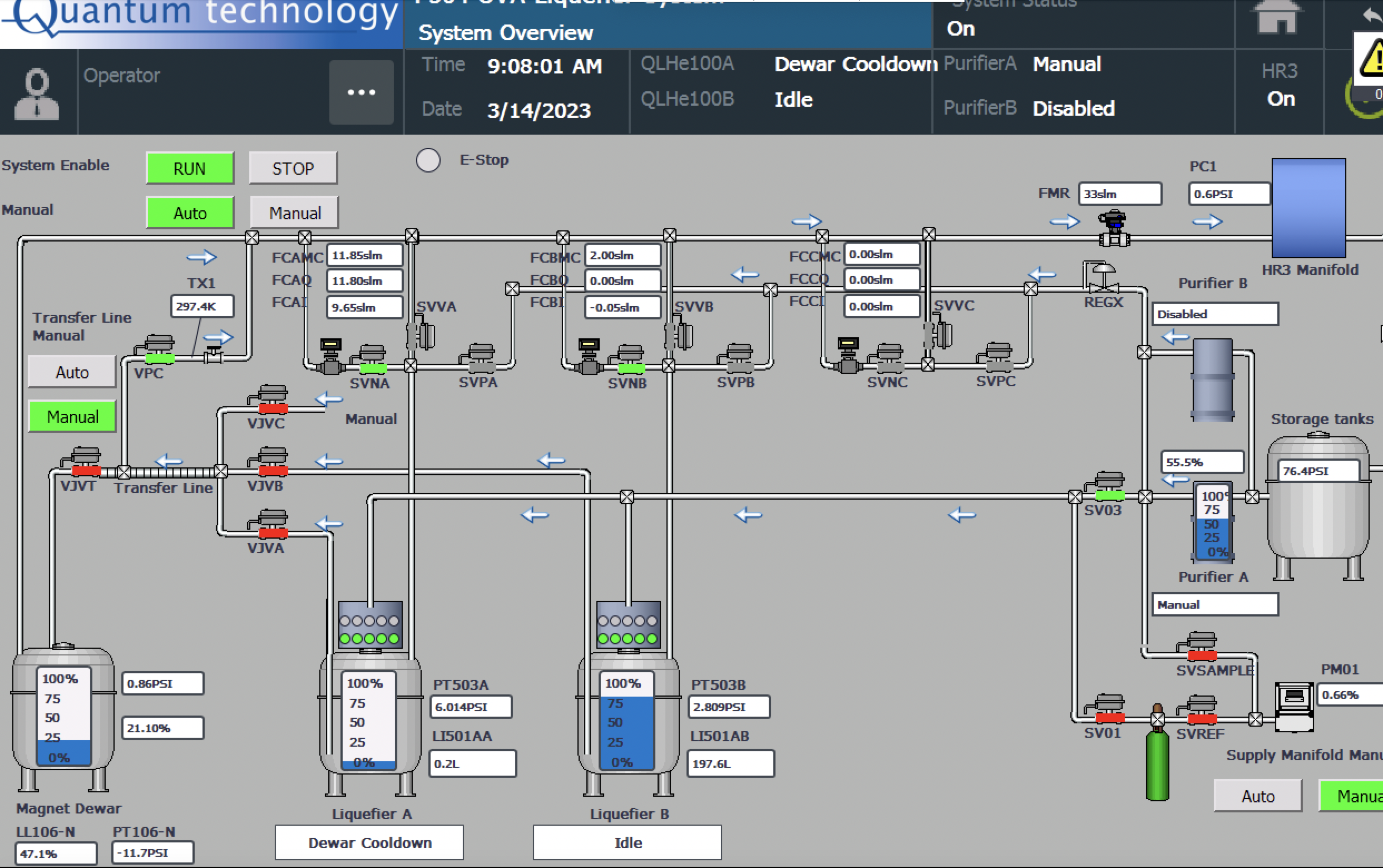
The overview screen (example)
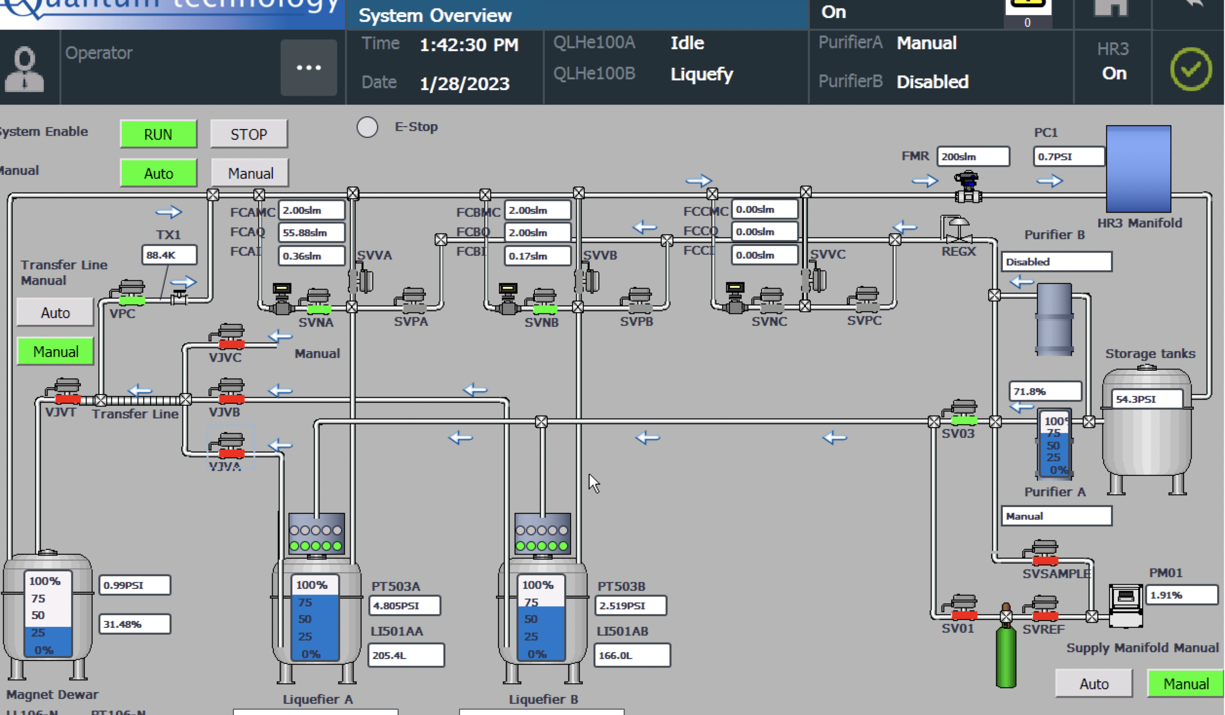
This example picture illustrates that both Liquefiers are "ON". Liquefier A is in "Idle" mode, whereas Liquefier B is in "Liquefy" mode.
("Idle" mode means, the Liquefier is just holding liquid helium at ~4 K but not producing).
Also, you can monitor the LHe, LN2 levels in the magnet, as well as the LN2 level in the purifier as well. Another example image is below.
Check each Liquerfier screens (A & B) at least once per hour. A sample operational screen is below.
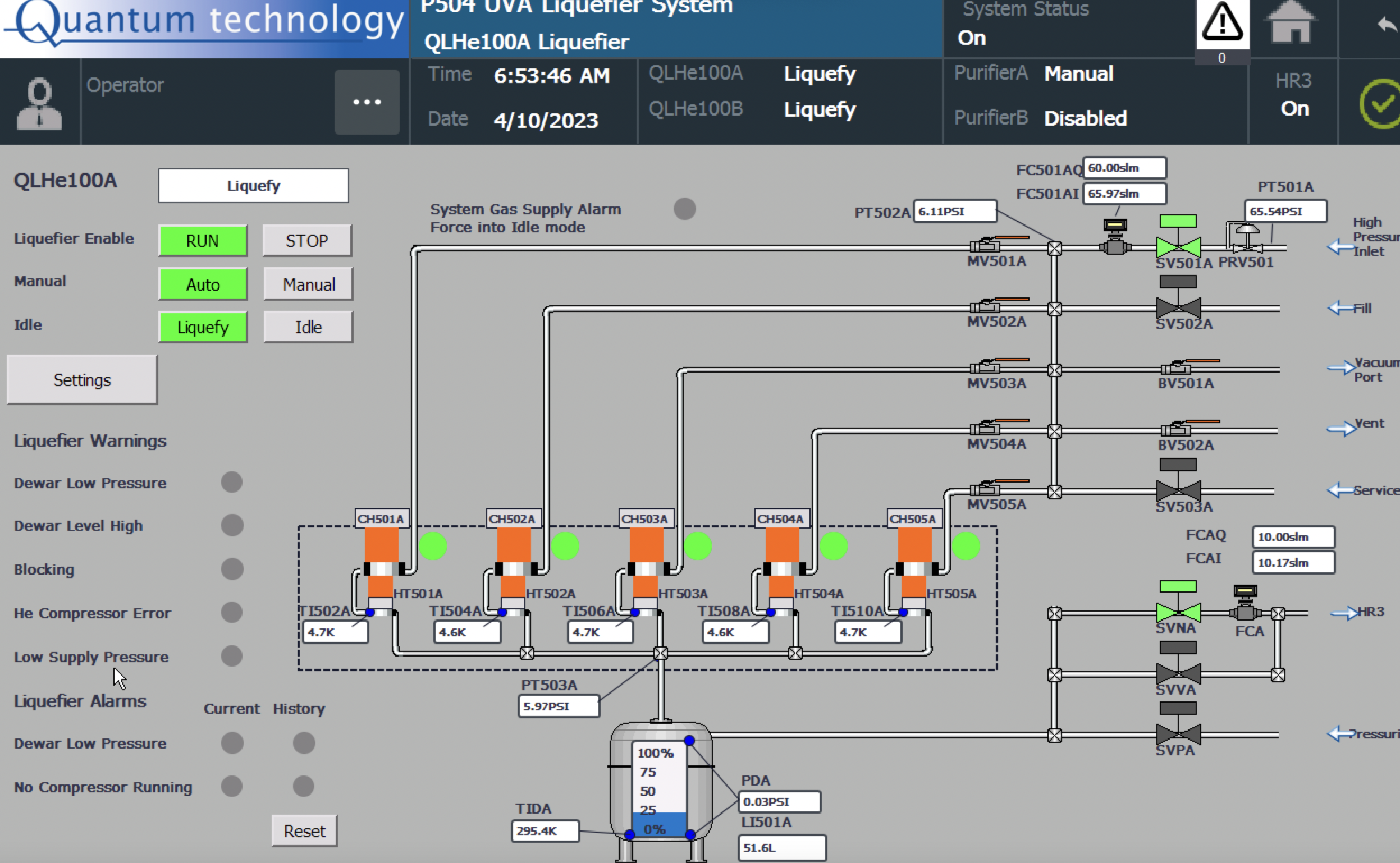
The main components to check on the Liquefier screens are below:
1) Mode (top left): Should be Run + Auto + Liquefy mode if it's in the production mode
2) Cold head temperatures: Should be around > 3 Kelvin.
3) Dewar level keeps increasing and does not do frequent large fluctuations between 0-275 Liters. If you start seeing large frequent fluctuations, then contact the Target Expert on shift immediately.
4) Make sure FC501(A/B)I (actual inlet gHe flow) is close to FC501(A/B)Q (gHe set-flow from PID) (see "Settings" screen to check the set values)
5) Make sure FC(A/B)I (actual outlet gHe flow) is close to FC(A/B)Q (gHe outlet set-flow from PID) (see "Settings" screen to check the set values)
In terms of the UVA-QT system maintenance, we need to keep the LN2 levels in the purifier always above 50% for higher production rate.
| Fill Procedure | Procedure |
|---|---|
| Filling LN2 to the purifier (remote: using the outside LN2 tank) | https://seaquest-docdb.fnal.gov/cgi-bin/sso/ShowDocument?docid=10337 |
| Filling LN2 to the purifier (in-person: using a portable LN2 Dewar) | https://seaquest-docdb.fnal.gov/cgi-bin/sso/ShowDocument?docid=10053 |
- Liquid helium fill procedure: https://seaquest-docdb.fnal.gov/cgi-bin/sso/ShowDocument?docid=9670
- In the liquid helium fill procedure; we do not need to set the "Dewar Set Pressure" to 3 psi because we swapped out the separator relief valve from 3 psi to 6 psi. So, the separator relief will not happen at 3 psi in the target cave.
- Liquid helium fill procedure: https://seaquest-docdb.fnal.gov/cgi-bin/sso/ShowDocument?docid=9670
Magnet LHe level: This LHe level should always be > 10% during the operational state. Monitor the level and arrange re-fills in a timely manner.
Note: Maximum level of the magnet is 45% due to the geometrical positioning of the level probe in the magnet.Purifier liquid nitrogen (LN2) level: This LN2 level should always be > 50%. Monitor the level and arrange re-fills in a timely manner.
Storage tank (gHe) pressure: This should be between 40 PSI and 110 PSI.
If the pressure reaches 110 PSI, then you will need to arrange to vent gHe to the atmosphere.
If the pressure is reaching 40 PSI, you will need to arrange a re-fill of gHe ahead of time.
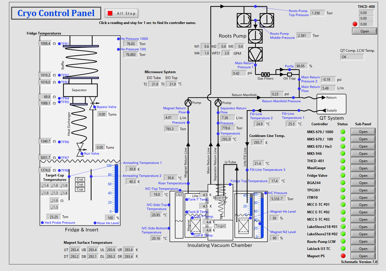
Cryo Control Panel (CCP)
It is a LabVIEW program (VI) that controls and monitors all cryogenic devices (except the QT Liquefier System). It is running on the target computer.
The target operator
- Checks the Main panel of CCP regularly (once every 5 minutes), and
- Call the target expert if any error appears on the Main panel of CCP, which usually marked with red indicator or red background color.
Main Panel of CCP
Move Target
The position of target cells is controlled by moving the target stick via the Target Lifter VI on the target computer. The run coordinator schedules the next target move.
The target operator moves the target at the scheduled time, by following the instructions below. If the Target Lifter VI shows any error or causes any unexpected condition, please call the target expert.
- Confirm that
- The beam is stopped and
- The microwave is stopped.
Make sure what is the destination location (i.e. "home", "annealing", "bottom", "top" or "middle").
Select the destination label from the drop-down menu in the Target Lifter VI.
Press “move”. Confirm that the red and blue progress bars update accordingly.
Keep eyes on the corresponding position switch indicator on the VI.
It will illuminate and stop the motion by itself.
If you see the progress bars update beyond the desired location, press the "STOP" button to stop the motion immediately, and call the target expert.
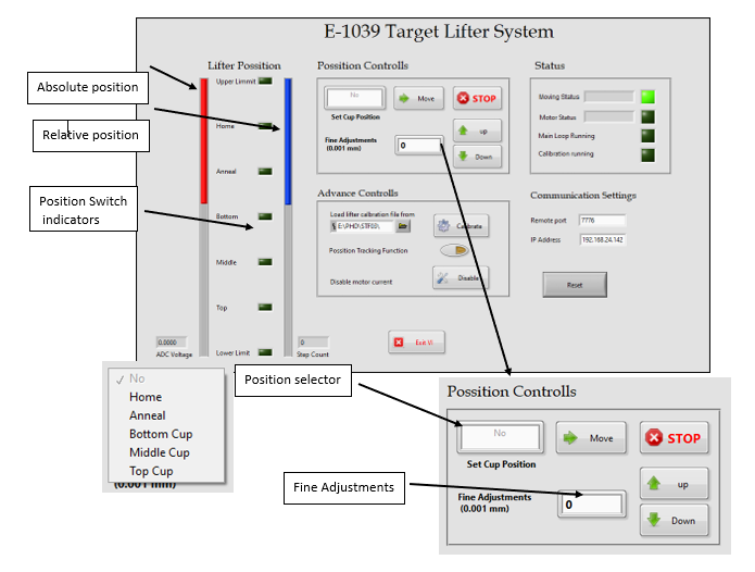
User Interface of Target Lifter VI
Change NMR
There are 2 NMR coils, one in the Top cup, one in the Bottom.
- Set the channel.
- Set the calibration constant.
- Select a baseline.
- Take Data and run DC Convert. Change Gain when needed.
Check Position
- Check that the beam is hitting the point on the target stick that it is suppose to
- Look at the Slow Raster images. Post them to the halog!
- Hot spots on the edges of the circle mean beam is crashing into our target cups!
- Destruction of target cups mean delays, make sure your shift worker is watching the slow raster!
Alarms and Safety
- Whenever there is any important event (major alarms, etc.) respond to the alarm first, then make screen grabs of the relevant target windows (PDP or Cryo Controls, charts, etc) and post them on the halog (with e-mail to the relevant experts, if needed)
- Correct the problem that caused the alarm before proceeding. Call if you think an expert should be consulted.
- Problems that don't cause alarms should be logged and experts consulted as needed, before proceeding.
Log Everything
Add to FNAL elog:
- Run, Separator Valve settings
- Microwave frequency, bellows position, polarization
- Target movement and new encoder value
- Alarms that don't go away by themselves
- Screengrab of PDP every hour
- For the screengrab, adjust the polarization graph to show how polarization has changed since the last screengrab.
- Screengrab of the cryo screen at the start of your shift
- Screengrab of the slow raster plot after a target movement.